

Selecting the correct tap involves much more than choosing the nominal thread size.
Two taps may both be marked:
1/4-20 UNC
or:
M8 × 1.25
yet have different pitch-diameter limits and therefore produce different internal thread sizes.
This is where tap-limit designations such as:
- H1
- H2
- H3
- H5
- GH2
- GH4
- OH2
- OH3
become important.
These markings are frequently misunderstood because they are not all part of one universal numbering system.
The most important principle is:
Tap limit is not the same thing as finished thread tolerance.
For example:
2B, 3B, 6H, and 6G describe thread tolerance requirements or classes of fit.
By contrast:
H, GH, and OH designations describe or help specify the pitch-diameter size of the tap itself under particular manufacturer or standards systems.
Gühring's technical guidance shows that every tap size and pitch has a basic pitch diameter from which H limits are established, while the finished thread class defines the permissible pitch-diameter range of the internal thread.
Understanding this distinction is essential for:
- Passing GO/NO-GO thread gauges
- Compensating for material behavior
- Extending tap life
- Preventing oversized threads
- Selecting taps from different manufacturers
- Specifying tools correctly in B2B purchasing
This guide explains H, GH, and OH tap limits, how they relate to thread classes such as 2B, 3B, and 6H, and how to choose the appropriate tap tolerance for actual machining conditions.
What Is Tap Pitch Diameter?
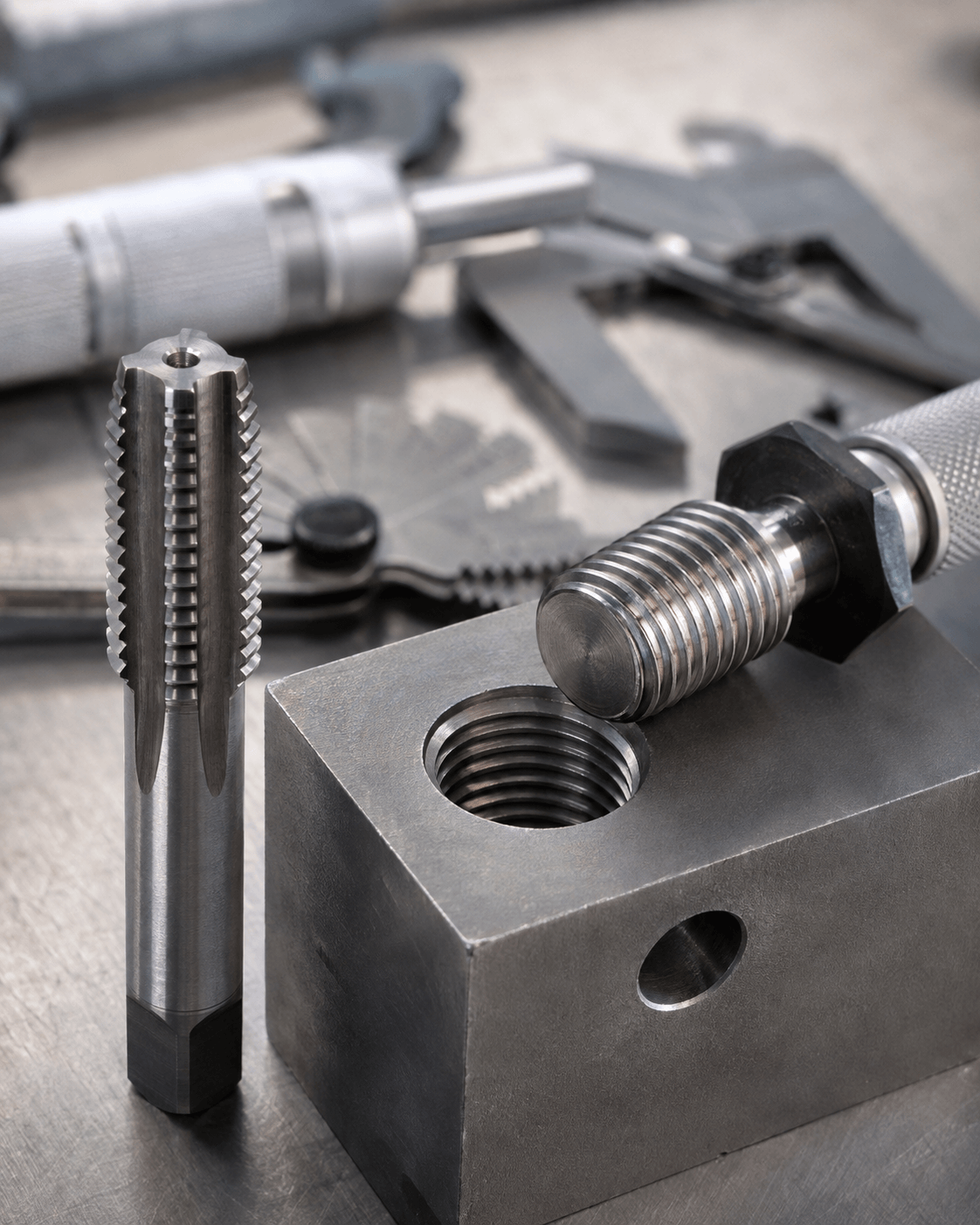
Before discussing tap limits, it is necessary to understand pitch diameter.
For a theoretical thread, pitch diameter is the diameter at which the widths of the thread ridge and groove are equal.
In practical tapping, pitch diameter is one of the most important dimensions controlling the fit between:
- Internal thread
- External screw or bolt
A tap therefore has its own controlled pitch diameter.
The finished internal thread also has an allowable pitch-diameter range.
These two ranges are related, but they are not identical. Gühring's DIN/ISO technical information explicitly distinguishes the tap thread profile and its pitch-diameter tolerance from the tolerance zone of the internal thread being produced.
What Is a Tap Limit?
A tap limit specifies where the tap's pitch diameter is positioned relative to a defined basic pitch diameter.
In the common U.S. H-limit system, higher H numbers generally represent progressively larger tap pitch diameters.
For example:
H1 < H2 < H3 < H4 < H5
in terms of pitch-diameter position.
This does not mean:
H5 is a higher-quality tap than H3.
It simply means:
H5 is manufactured with a larger pitch-diameter limit.
The number describes size position, not quality grade.
Why Are Taps Manufactured Above Basic Pitch Diameter?
A cutting tap must produce an internal thread with enough dimensional margin to remain acceptable as the tap wears.
If a new tap started too close to the minimum acceptable internal-thread pitch diameter, relatively little wear could cause the thread to become too tight.
Manufacturers therefore select tap pitch-diameter limits so that the tool operates within a useful part of the allowable finished-thread tolerance zone. Gühring illustrates the way H limits sit relative to 1B, 2B, and 3B internal-thread tolerance zones.
The objective is to balance:
Initial thread size + Wear allowance + Risk of oversize
The Most Important Rule
A higher tap limit generally tends to produce a larger internal-thread pitch diameter.
A lower tap limit generally tends to produce a tighter internal thread.
But:
Finished thread pitch diameter does not equal tap pitch diameter exactly.
Actual tapping behavior can shift the finished thread because of:
- Runout
- Machine alignment
- Material deformation
- Cutting-edge geometry
- Lubrication
- Synchronization
- Tool wear
This is why selecting a tap limit only from a theoretical chart can sometimes produce unexpected gauge results.
Understanding the H-Limit System
H limits are widely used for inch-series taps in North American tooling.
In the conventional system, the pitch-diameter range is divided into incremental steps above the basic pitch diameter.
Gühring describes these H limits as progressing in increments of 0.0005 inch in its UNC/UNF technical chart.
For the common range illustrated by this convention:
H1
Basic pitch diameter to:
Basic + 0.0005 in
H2
Basic + 0.0005 to:
Basic + 0.0010 in
H3
Basic + 0.0010 to:
Basic + 0.0015 in
H4
Basic + 0.0015 to:
Basic + 0.0020 in
H5
Basic + 0.0020 to:
Basic + 0.0025 in
H6
Basic + 0.0025 to:
Basic + 0.0030 in
H7
Basic + 0.0030 to:
Basic + 0.0035 in
The exact applicable convention should always be confirmed from the manufacturer's technical data, especially outside common standard diameter ranges. Gühring's published chart uses the same 0.0005-inch progression to illustrate the H-limit relationship with UNC/UNF thread classes.
Higher H Number Does Not Mean Looser Thread Class
This is a critical distinction.
Consider:
H3
and:
H5
These are tap-size limits.
Now consider:
2B
and:
3B
These are internal-thread classes.
They describe different things.
A Class 3B internal thread has a different permitted tolerance range from a Class 2B thread. The appropriate tap limit must therefore be selected so that the actual tapping process produces the required finished thread within that range. Gühring identifies 2B as the common general-purpose class and 3B as a more precision-oriented class while showing their different pitch-diameter tolerance bands.
Example: H Limit for a 2B Thread
Consider a:
1/4-20 UNC-2B
thread.
The tap should not simply be ordered as:
1/4-20 tap
without considering the intended thread class.
Manufacturer recommendations commonly assign an appropriate H limit based on the expected relationship between:
- Tap pitch diameter
- Finished 2B tolerance
- Normal cutting enlargement
For example, GWS Tool Group's technical guidance gives H5 as a recommended H limit for a 1/4-20 UNC-2B application under its normal selection approach, while it gives H3 for the corresponding 3B application.
This illustrates an important principle:
A tighter finished thread class may require a different tap limit even when nominal diameter and pitch are identical.
What Is GH?
GH is another designation encountered on taps, especially in catalogs using an ANSI-style ground-tap classification.
Yamawa describes its GH tap-class approach for Unified threads as being based on an ANSI GH system with pitch-diameter steps of 12.7 μm, which is equivalent to 0.0005 inch.
Tapmatic's technical documentation explains the nomenclature as:
- G = ground thread
- H = pitch diameter on the high side of basic
followed by a number indicating the pitch-diameter oversize range.
Therefore, designations such as:
- GH1
- GH2
- GH3
- GH4
- GH5
represent progressively higher pitch-diameter tap classes in that system.
H vs. GH: Are They the Same?
They are closely related in the common ANSI-style system, but purchasing teams should avoid treating every catalog marking as automatically interchangeable.
For example:
H3
and:
GH3
may both refer to the familiar 0.0005-inch-step high-side pitch-diameter framework when the manufacturer uses that convention. Yamawa explicitly states that its GH system follows the 12.7 μm step basis of the ANSI GH class.
However, when buying taps from different manufacturers, always check:
- Manufacturer tolerance chart
- Tap standard
- Thread standard
- Finished thread class
- Tool type
Do not rely only on the similarity of the letters.
GH Classes and Finished Thread Tolerance
Yamawa's published Unified-thread tables show different GH recommendations depending on:
- Thread diameter
- Pitch
- 2B requirement
- 3B/UNJ requirement
For example, the recommended GH class is not universally GH3 for every 2B thread. The recommended value changes across different sizes and pitches.
This is important because it prevents a common purchasing mistake:
There is no universal “best GH number” for all UNC/UNF taps.
Thread size matters.
What Is OH?
OH is a different tolerance system and should not be treated as another spelling of H or GH.
OSG uses an OH precision system for cutting taps, and its published documentation shows that the incremental change between OH classes depends on thread pitch.
For OSG cutting taps:
For pitch:
P ≤ 0.6 mm
one OH step corresponds to approximately:
15 μm
For pitch:
P ≥ 0.7 mm
one OH step corresponds to approximately:
20 μm
OSG gives the example that if a cutting tap with pitch 0.7 mm or greater has:
STD = OH3
then:
STD + 1 = OH4
is 0.02 mm larger in pitch diameter, and:
STD + 2 = OH5
is 0.04 mm larger than the STD tap.
Why OH3 Is Not the Same as H3
This is perhaps the most important point in the entire article.
Consider the numerical step sizes.
A conventional H/GH step:
0.0005 in ≈ 12.7 μm
An OSG OH step for a cutting tap with pitch ≥ 0.7 mm:
20 μm
Therefore:
OH3 ≠ H3
and:
OH3 ≠ GH3
simply because the number “3” is the same.
The systems use different reference structures and different increments.
Do Not Convert H3 Directly to OH3
Suppose a factory currently uses:
M8 × 1.25 OH3
and a buyer wants to source a replacement tap from another supplier using an H/GH system.
Ordering:
H3
or:
GH3
only because the old tool says OH3 can produce the wrong pitch diameter.
Instead compare the actual:
Tap pitch-diameter specification
The purchasing process should be:
Old tap specification
→ Actual pitch-diameter range
→ Required finished-thread tolerance
→ New manufacturer's tolerance system
→ Equivalent recommended tool
This is much safer than matching tolerance numbers visually.
OH “STD” Can Differ Between Tap Products
Another important feature of the OH system is that the manufacturer's standard recommended tap limit does not necessarily use one OH number for every diameter.
OSG product data provides examples where standard cutting taps use different OH limits depending on size and application. For example, OSG listings show standard products using OH2 for some metric sizes and OH3 for others.
Therefore:
STD does not mean one universal OH number.
It means the manufacturer's standard recommended tap tolerance for that particular tool/application.
Why Manufacturers Use Different Standard Limits
The tap does not always cut exactly at its measured pitch diameter.
Actual thread size can be influenced by:
- Workpiece material
- Machine type
- Tap geometry
- Cutting behavior
OSG explains, for example, that it adjusted the standard tolerance of some tap sizes from OH2 to OH3 based on observed reduction in cutting enlargement under certain machining-center conditions.
This demonstrates why tap tolerance selection is ultimately an application decision rather than simply a theoretical conversion exercise.
H, GH, and OH: Quick Comparison
H
Commonly encountered in:
North American inch-thread tap specifications
Typical concept:
Incremental pitch-diameter limits above basic
Typical common increment:
0.0005 inch
Examples:
H1, H2, H3, H4, H5
GH
Used by manufacturers following an ANSI-style ground-thread tap classification.
Typical concept:
Ground tap, high-side pitch-diameter classes
Yamawa's ANSI-based GH system uses:
12.7 μm / 0.0005 inch steps.
Examples:
GH1, GH2, GH3, GH4, GH5
OH
OSG cutting-tap precision system.
Increment depends on pitch.
OSG states:
P ≤ 0.6 → 15 μm per class
P ≥ 0.7 → 20 μm per class.
Examples:
OH1, OH2, OH3, OH4
The practical conclusion is:
H/GH and OH should not be converted by matching the class number.
Thread Class vs. Tap Class
This distinction deserves repeating.
Suppose a drawing specifies:
1/4-20 UNC-2B
The 2B requirement applies to the finished internal thread.
The tap may be:
H4
H5
or another appropriate limit depending on the production condition.
Similarly, a metric drawing may specify:
M8 × 1.25-6H
The 6H applies to the finished internal thread tolerance zone.
The tap itself may be specified using:
- ISO/DIN tap tolerance
- Manufacturer OH system
- Another manufacturer-specific tooling class
depending on the supplier.
Gühring's ISO technical guide notes that the tolerance class of a tap is related to the internal thread it is intended to produce but is not necessarily identical to the actual tolerance zone of every finished internal thread produced in practice.
Understanding Metric 6H
For ISO metric internal threads, a designation such as:
M10 × 1.5-6H
contains several pieces of information.
M10:
Nominal thread diameter
1.5:
Pitch
6H:
Internal-thread tolerance class
In this designation:
6 describes the tolerance grade.
H describes the tolerance-zone position.
This H should not be confused with:
H3 tap limit
used in the North American H-limit system.
They belong to different nomenclature systems.
ISO Tap Application Classes
DIN/ISO tap systems may also use application classes associated with internal-thread tolerance zones.
Gühring's DIN EN 22857 technical information shows examples involving classes such as:
- 4H
- 6H
- 6G
- 7G
and corresponding tap application classifications.
This is another reason a tap should never be purchased from the word:
“H”
alone.
You need the complete tolerance designation and standard.
Why Higher Tap Limits Can Increase Tool Life
Imagine the acceptable finished thread tolerance as a window.
A tap that begins near the lower boundary has relatively little room to become smaller as it wears.
A tap beginning farther into the acceptable tolerance zone may provide more wear allowance.
This can extend the number of acceptable holes before the finished thread becomes too tight.
GWS Tool Group describes a commonly used selection approach that positions the tap within the part tolerance rather than at the extreme minimum, while warning against choosing so high a limit that normal cutting enlargement produces an oversized thread.
The goal is:
Maximum useful wear allowance without exceeding the upper finished-thread limit.
Why You Cannot Simply Choose the Highest H Limit
Suppose a thread tolerance permits H3 through H5 theoretically.
It may appear logical to select H5 because it gives greater wear allowance.
But the tap may cut larger than its measured size.
If:
- Runout is high
- Workpiece expands during cutting
- Machine alignment is poor
the H5 tap may produce an oversized internal thread.
Therefore:
Higher H limit can improve wear allowance, but also reduces oversize safety margin.
The “40% Rule”
One tap-industry selection practice described by GWS Tool Group is to position the tap approximately 40% into the allowable finished-thread tolerance zone under normal tapping conditions.
This creates margin for:
- Cutting enlargement
- Tool wear
However, it should be treated as:
A selection guideline
rather than a universal engineering law.
The actual optimum can change with material and process behavior.
Material Springback
The finished thread may change after the cutting edges pass through it.
Some materials may recover elastically or otherwise produce a finished thread that behaves tighter than expected.
When this occurs, a somewhat larger tap pitch diameter may be required.
This is one reason manufacturers provide multiple tap-limit options rather than one fixed tool size for every nominal thread.
Cutting Enlargement
The opposite condition can also occur.
The finished thread may become larger than the tap's nominal cutting expectation because of:
- Runout
- Deflection
- Machine condition
If the process consistently cuts large:
A lower tap limit may be appropriate.
This should be validated with actual thread-gauge results.
Runout Can Change the Required Tap Limit
Suppose a tap theoretically has the perfect pitch diameter.
If radial runout causes the tap to orbit slightly inside the pre-hole, the effective cut can become larger.
Symptoms may include:
- Oversized thread
- Uneven tap wear
- Reduced tool life
Before switching from:
H5 → H3
verify:
- Tap runout
- Holder condition
- Spindle runout
Otherwise, changing tap limit may only hide a mechanical problem.
Machine Synchronization
Rigid tapping errors can also influence thread quality.
Incorrect spindle/feed synchronization can introduce:
- Axial loading
- Thread flank distortion
- Tool wear
A tap-limit change should therefore not be the first response to every gauge failure.
The complete tapping system matters.
Tap Drill Size
Tap drill size primarily affects:
- Thread engagement
- Cutting torque
- Minor diameter
while tap limit primarily controls the tap's pitch-diameter relationship.
These are different variables.
Do not attempt to correct every pitch-diameter problem simply by changing the pre-hole size.
A thread can have an acceptable minor diameter while failing pitch-diameter gauge inspection.
Tool Wear and Tap Limit
As a cutting tap wears, its effective cutting size can decrease.
A typical pattern may be:
New tap:
Thread comfortably passes GO gauge.
Mid-life:
Thread moves toward tighter side.
End-of-life:
GO gauge becomes difficult or fails.
Selecting the correct initial tap limit creates enough dimensional margin to use the tool economically without allowing new-tool threads to start oversize.
Tap Limit and GO/NO-GO Gauges
The finished thread—not the marking on the tap—is ultimately what must satisfy the engineering requirement.
For an internal thread:
GO gauge checks one functional boundary.
NO-GO gauge checks the opposite tolerance condition according to the relevant gauge standard.
Therefore:
Correct H limit does not eliminate the need for thread inspection.
The tap limit is a manufacturing tool selection parameter.
The gauge determines whether the resulting thread is acceptable.
A Tap Marked H5 Does Not Guarantee a 2B Thread
This is a common B2B purchasing misunderstanding.
A customer may say:
“We need H5 because our thread is 2B.”
But H5 alone cannot guarantee 2B.
The resulting thread still depends on:
- Nominal thread size
- Material
- Tap condition
- Runout
- Machine
- Workholding
- Lubrication
Gühring's chart specifically shows that H-limit relationships vary across the allowable tolerance windows rather than representing a one-to-one universal class conversion.
2B vs. 3B Tap Selection
For Unified internal threads:
2B is commonly used for general-purpose threaded products.
3B has a narrower tolerance and is associated with more closely controlled applications. Gühring illustrates these classes as different overlapping but progressively tighter pitch-diameter tolerance bands.
Because 3B provides less available tolerance, tap-limit selection becomes more sensitive.
A tap suitable for 2B should therefore not automatically be assumed suitable for 3B.
Oversize Taps
Sometimes a manufacturer intentionally uses an oversized tap.
Applications can include processes where the internal thread will become tighter later.
OSG identifies situations such as:
- Subsequent plating
- Subsequent heat treatment
- Workpieces with springback behavior
as reasons oversized tap tolerances may be selected.
Plating Compensation
Suppose a thread is tapped before:
- Zinc plating
- Nickel plating
- Other surface treatment
The deposited layer changes the available thread clearance.
If the pretreatment thread is produced too tight, the thread may fail assembly or gauge inspection after coating.
An oversized tap may therefore be specified so that the final coated thread falls within the required tolerance.
The amount should be determined from the actual coating process rather than by arbitrarily adding several H or OH classes.
Do Not Guess the Oversize Amount
A common mistake is:
“We have plating, so use H7.”
That is not enough information.
You need to know:
- Coating system
- Expected dimensional effect
- Finished thread requirement
- Tap standard
- Existing process behavior
Then specify the appropriate tap pitch diameter.
Form Taps Require Special Attention
Do not assume that the same H/OH system applies to every forming tap.
For example, OSG states that it uses:
OH precision for cutting taps
but:
RH precision for roll/form taps.
Yamawa also describes its own roll-tap G-class system based on 12.7 μm steps derived from the ANSI GH concept.
Therefore, when switching from:
Cutting tap → Form tap
recheck the manufacturer's tolerance system from the beginning.
Why Form Taps Are More Sensitive to Pre-Hole Size
A cutting tap removes material.
A form tap displaces material.
Therefore, pre-hole diameter strongly influences how material flows into the thread profile.
Even if the form-tap pitch diameter is correct, an incorrect pre-hole can produce:
- Excessive torque
- Incorrect minor diameter
- Poor thread formation
Tap tolerance and pre-hole tolerance must therefore be evaluated together.
Comparing Taps From Different Suppliers
Suppose Supplier A lists:
1/4-20 H5
Supplier B lists:
1/4-20 GH5
Supplier C supplies a tool under another tolerance system.
Do not compare only the number.
Request:
- Actual pitch-diameter range
- Applicable standard
- Recommended finished thread class
This allows a proper technical comparison.
B2B Purchasing Specification
Instead of sending a purchase order that says:
M8 Tap
use a more complete specification such as:
M8 × 1.25, internal thread 6H, blind hole, spiral flute, cutting tap, required manufacturer's recommended tap tolerance
For Unified threads:
1/4-20 UNC-2B, spiral point, through hole, H/GH limit per supplier recommendation
If your process already requires a validated tap pitch diameter, specify that as well.
Never Use the Number Alone
The following purchase request is incomplete:
Need H3 taps.
H3 of what?
You still need:
- Thread size
- Pitch
- Thread standard
- Required class
- Tool type
Tolerance designation only has meaning in context.
Practical Example 1: 1/4-20 UNC-2B
Suppose production requires:
1/4-20 UNC-2B
The factory uses a rigid CNC tapping machine with:
- Low runout
- Stable steel material
- Controlled coolant
A manufacturer may recommend an H limit around the normal 2B production range; GWS, for example, lists H5 for its 1/4-20 UNC-2B selection example.
The factory should then validate:
- GO gauge
- NO-GO gauge
- New tap results
- End-of-life results
If H5 produces oversize threads, investigate process enlargement before automatically ordering H4 or H3.
Practical Example 2: 1/4-20 UNC-3B
Now change only the finished tolerance requirement to:
3B
The allowable finished thread range is tighter.
GWS's example recommends H3 rather than H5 for this 1/4-20 UNC-3B case.
This demonstrates that nominal thread size alone is insufficient for tap selection.
Practical Example 3: M8 × 1.25 OH Tap
Suppose an OSG cutting tap is listed as:
M8 × 1.25 OH3
Because the pitch is greater than 0.7 mm, OSG's OH system uses a 20 μm step between adjacent OH classes.
Moving to:
OH4
therefore represents a larger pitch-diameter class than OH3.
But replacing it with:
GH4
from a different system would not mean the same dimensional change.
Practical Example 4: Thread Becomes Tight After Plating
Suppose:
Before coating:
GO gauge passes easily.
After coating:
GO gauge fails.
Do not simply change the tap without data.
Measure:
- Thread before coating
- Thread after coating
- Coating effect
- Required finished tolerance
Then choose the required tap oversize.
OSG specifically identifies post-tapping plating as an application for intentional oversized tap selection.
Practical Example 5: New Tap Already Produces Oversize Threads
A higher tap limit is not appropriate.
Investigate:
- Toolholder runout
- Spindle runout
- Misalignment
- Tap geometry
- Machine synchronization
If the complete process is stable but the thread consistently remains too large:
A lower tap pitch-diameter limit may be needed.
Practical Example 6: Thread Passes Initially but Quickly Becomes Tight
This may indicate insufficient wear allowance.
Possible causes include:
- Tap limit too low
- Rapid tap wear
- Abrasive material
- Poor coating selection
- Insufficient lubrication
If the tap itself remains otherwise healthy, a higher tap limit may provide additional tool life—but only if new-tool threads remain safely below the maximum allowable thread size.
Tap Limit Optimization for Tool Life
A useful production objective is to track thread size through the tap's full life.
For example:
New Tap
Thread near upper-middle of allowable range.
Mid-Life
Thread moves gradually smaller.
End of Life
Thread approaches minimum acceptable functional boundary.
This uses more of the available tolerance window.
By contrast, if a new tap already produces a thread near the minimum boundary:
Tool wear allowance is being wasted.
But Do Not Chase Maximum Gauge Life Blindly
Suppose increasing from H4 to H5 gives:
20% longer tap life.
But H5 also produces occasional NO-GO failures when:
- Runout increases
- Material batch changes
Then H4 may still be the more economical process.
The correct target is:
Maximum predictable acceptable holes
not:
Maximum possible tap life under ideal conditions.
Tap Regrinding and Limits
Regrinding can change effective tap geometry and dimensional margin.
After repeated reconditioning, the tap may produce a progressively tighter thread.
For taps that are reground, monitor:
- Tap pitch diameter
- GO/NO-GO results
- Regrind generation
Do not assume a reconditioned H5 tool performs dimensionally exactly like a new H5 tool.
Coating and Tap Pitch Diameter
Recoating can also affect the finished tool dimensions.
For precision tapping, grinding and coating processes should be coordinated so the finished tap still meets its specified pitch-diameter limit.
This becomes especially important when thread tolerances are tight.
Common Mistake 1: Assuming H3 Means 3B
It does not.
H3 = Tap pitch-diameter limit
3B = Finished Unified internal-thread class
These are different specifications.
Common Mistake 2: Assuming OH3 = GH3
Incorrect.
The systems use different incremental structures.
OSG OH cutting-tap steps can be 15 or 20 μm depending on pitch, whereas Yamawa's ANSI-based GH framework uses 12.7 μm steps.
Common Mistake 3: Assuming Higher Number Means Higher Accuracy
H5 is not “better” than H3.
OH4 is not “higher quality” than OH2.
The number primarily describes pitch-diameter size position within that system.
Common Mistake 4: Choosing the Largest Available Limit for Tool Life
This may produce oversized threads.
Tool-life margin must remain inside the finished-thread tolerance.
Common Mistake 5: Solving Runout With Tap Limit
If the machine is cutting oversize because of runout, using a smaller tap may temporarily make the gauge pass.
But the underlying mechanical instability remains.
Correct the runout first.
Common Mistake 6: Ignoring Material Behavior
The same tap may produce slightly different finished thread behavior in different materials.
A tolerance validated in one material should not automatically be transferred to another critical application.
Common Mistake 7: Ignoring Coating or Heat Treatment
The thread condition at final assembly matters.
If downstream processing changes thread dimensions, tap selection must account for it.
Common Mistake 8: Using Cutting-Tap Tolerances for Form Taps
The manufacturer's tolerance system may be different.
Always check the form-tap catalog separately.
Troubleshooting: GO Gauge Will Not Enter
Possible causes include:
- Tap pitch diameter too small
- Tap worn
- Material recovery
- Incorrect tap tolerance
- Built-up edge
- Thread damage
Before increasing H/OH/GH limit, verify tool condition and process stability.
Troubleshooting: NO-GO Gauge Enters Too Far
Possible causes include:
- Tap limit too large
- Excessive runout
- Machine misalignment
- Wrong thread specification
Do not automatically blame the tap tolerance.
Measure the actual process.
Troubleshooting: Threads Become Tight as Tap Wears
Some gradual tightening is expected as a cutting tap loses effective size.
If this occurs too quickly, investigate:
- Tool material
- Coating
- Cutting speed
- Lubrication
- Abrasive workpiece behavior
A different tap limit can increase wear allowance, but only after wear rate itself has been evaluated.
Troubleshooting: Different Suppliers Produce Different Gauge Results
Confirm whether the suppliers are actually providing identical:
- Tap pitch diameter
- Tolerance system
- Thread geometry
“H3,” “GH3,” “OH3,” and “6H” should never be assumed to be interchangeable specifications.
A Practical Tap-Limit Selection Workflow
Step 1: Read the Part Drawing
Identify:
- Thread diameter
- Pitch/TPI
- Thread standard
- Finished tolerance
For example:
1/4-20 UNC-2B
or:
M8 × 1.25-6H
Step 2: Identify the Tap System
Determine whether the supplier uses:
- H
- GH
- OH
- ISO/DIN application class
- Another proprietary system
Step 3: Check the Manufacturer's Tolerance Chart
Do not convert by memory.
Use the actual published specification.
Step 4: Check the Tool Type
Is it:
- Cutting tap
- Form tap
The tolerance system may change.
Step 5: Evaluate Material Behavior
Does the process tend to:
- Cut oversize
- Produce tight threads
- Require post-machining coating
Step 6: Verify Machine Condition
Measure:
- Runout
- Alignment
- Synchronization
Step 7: Test the Recommended Limit
Use production conditions, not a bench test alone.
Step 8: Gauge New Threads
Check GO/NO-GO results.
Step 9: Gauge Threads Through Tool Life
Monitor dimensional drift.
Step 10: Optimize the Limit
Choose the tap that maximizes:
Acceptable tool life without exceeding finished-thread tolerance.
What Should B2B Buyers Ask a Tap Supplier?
When requesting a quotation, ask:
- What tap-limit system do you use?
- What is the actual pitch-diameter tolerance?
- Which finished thread class is this tap intended to produce?
- Is the recommended limit different for my material?
- Is oversize available?
- How should I specify taps for plated parts?
- Is the tolerance designation different for form taps?
A competent supplier should be able to provide more information than simply:
“This is an H3 tap.”
Recommended RFQ Information
For a more accurate quotation, provide:
Thread: M10 × 1.5
Finished tolerance: 6H
Material: Carbon steel
Hole: Blind
Thread depth: 15 mm
Process: CNC rigid tapping
Tap type: Spiral flute cutting tap
Surface treatment after tapping: None
This allows the supplier to recommend the correct tool tolerance rather than guessing.
Quick Reference
H
Primarily:
Tap pitch-diameter limit
Common U.S. increment:
0.0005 inch
Higher number:
Larger tap pitch diameter
GH
ANSI-style ground-tap classification used by some manufacturers.
Typical increment:
12.7 μm / 0.0005 inch
Higher number:
Larger tap pitch-diameter class
OH
OSG cutting-tap tolerance system.
OSG step values:
Pitch ≤ 0.6 mm → 15 μm
Pitch ≥ 0.7 mm → 20 μm
Higher number:
Larger tap pitch diameter
2B / 3B
Finished Unified internal-thread tolerance classes.
They are:
Not tap H-limit numbers
6H
ISO metric internal-thread tolerance designation.
It is:
Not equivalent to H6
and:
Not equivalent to OH6
The Most Important Purchasing Rule
Never compare:
H3 vs. GH3 vs. OH3
by number alone.
Compare:
Actual tap pitch diameter + Finished thread requirement + Manufacturing process
instead.
Final Tap-Limit Checklist
Before ordering a tap, confirm:
Thread Requirement
- Nominal diameter
- Pitch or TPI
- Thread standard
- Finished tolerance class
Tap Specification
- H / GH / OH / ISO system
- Actual pitch-diameter limit
- Cutting or forming tap
- Standard or oversize
Process
- Material
- Through or blind hole
- Machine type
- Holder/runout
- Lubrication
Post-Processing
- Plating
- Coating
- Heat treatment
Validation
- GO gauge
- NO-GO gauge
- New-tool thread size
- End-of-life thread size
Conclusion
H, GH, and OH tap-limit markings all help describe tap pitch-diameter control, but they should not be treated as one universal numbering system.
For the conventional H-limit system:
Higher H number → Larger tap pitch-diameter limit
with common H increments of:
0.0005 inch in the standard range illustrated by manufacturer technical charts.
For ANSI-style GH classifications, manufacturers such as Yamawa use:
12.7 μm / 0.0005 inch increments.
For OSG's OH cutting-tap system, the step is different:
15 μm for pitch ≤ 0.6 mm
and:
20 μm for pitch ≥ 0.7 mm.
Therefore:
H3 ≠ automatically GH3 ≠ automatically OH3
when tools are being compared across different catalog systems.
More importantly:
Tap tolerance ≠ Finished thread tolerance
A part drawing may specify:
2B, 3B, or 6H
while the tap itself requires an appropriate:
H, GH, OH, or ISO/DIN tap tolerance
to produce that finished thread reliably.
The best tap limit is not simply the largest number that still appears to pass a gauge.
It is the limit that provides:
Adequate wear allowance + Stable thread size + Low rejection risk + Predictable tool life
under the actual production conditions.
For purchasing and process engineering, the safest rule is:
Start with the required finished thread class, identify the manufacturer's tap-tolerance system, compare actual pitch-diameter limits, and validate the result with production gauging.
That approach prevents one of the most common errors in tap selection: assuming that similar-looking tolerance markings from different systems mean the same thing.


